
741 Op Amp Pinout Wiring Diagram: A Comprehensive Guide
Understanding the 741 operational amplifier (op amp) pinout is crucial for anyone working with analog electronics. The 741 op amp is one of the most widely used op amps in the industry, and its versatile design makes it suitable for a wide range of applications. In this article, we will delve into the details of the 741 op amp pinout wiring diagram, providing you with a comprehensive guide to help you get the most out of this iconic component.
Pin Configuration

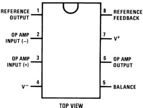
The 741 op amp has eight pins, which are arranged in a standard dual-in-line package (DIP). The pin configuration is as follows:
| Pin Number | Description |
|---|---|
| 1 | Inverting Input (-) |
| 2 | Non-Inverting Input (+) |
| 3 | Output |
| 4 | Collector Output |
| 5 | Emitter Output |
| 6 | Power Supply (Vcc) |
| 7 | Ground (GND) |
| 8 | Power Supply (Vcc) |
It’s important to note that pins 6 and 8 are both power supply pins, which means you can connect either one to the positive voltage source, and the other to ground. This flexibility makes the 741 op amp even more versatile.
Wiring the 741 Op Amp

Now that we have a clear understanding of the pin configuration, let’s discuss how to wire the 741 op amp. The following steps will guide you through the process:
- Connect the power supply (Vcc) to pin 6 or 8. Ensure that the voltage is within the recommended range, which is typically between 5V and 15V.
- Connect the ground (GND) to pin 7.
- Connect the inverting input (-) to the input signal you want to amplify.
- Connect the non-inverting input (+) to a reference voltage or directly to ground, depending on the desired configuration.
- Connect the output to the load or the next stage in your circuit.
It’s worth mentioning that the 741 op amp has a high input impedance, which means it draws very little current from the input signal. This makes it an ideal choice for many applications, including amplifiers, filters, and oscillators.
Common Configurations
The 741 op amp can be configured in various ways to suit different applications. Here are some of the most common configurations:
Non-Inverting Amplifier
In a non-inverting amplifier configuration, the non-inverting input (+) is connected to the input signal, and the inverting input (-) is connected to ground. The gain of the amplifier is determined by the ratio of the feedback resistor (Rf) to the input resistor (Rin). The formula for gain is:
Gain = 1 + (Rf / Rin)
Inverting Amplifier
In an inverting amplifier configuration, the inverting input (-) is connected to the input signal, and the non-inverting input (+) is connected to ground. The gain is determined by the ratio of the feedback resistor (Rf) to the input resistor (Rin). The formula for gain is:
Gain = – (Rf / Rin)
Buffer Amplifier
A buffer amplifier is used to isolate the input signal from the load, preventing the load from affecting the signal quality. In a buffer amplifier configuration, the non-inverting input (+) is connected to the input signal, and the inverting input (-) is connected to ground. The gain is equal to 1.