
Adder Circuit with Op Amp: A Detailed Multidimensional Introduction
When it comes to electronic circuits, the adder circuit is a fundamental building block that allows for the addition of two or more numbers. One of the most common and efficient ways to implement an adder is by using an operational amplifier (op amp). In this article, we will delve into the intricacies of an adder circuit with an op amp, exploring its design, operation, and applications.
Understanding the Basics

An op amp is an electronic device that amplifies the difference between two input voltages. It is a versatile component that can be used in various applications, including signal conditioning, filtering, and mathematical operations like addition. An adder circuit with an op amp is designed to add two or more input voltages and produce a single output voltage that represents the sum of the inputs.
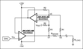
The basic configuration of an adder circuit with an op amp involves three inputs: two input voltages (V1 and V2) and a third input that is connected to ground. The output voltage (Vout) is the sum of the input voltages. The circuit typically consists of an op amp, resistors, and capacitors.
Designing the Adder Circuit
Designing an adder circuit with an op amp requires careful consideration of the component values. The resistors and capacitors in the circuit determine the gain, input impedance, and output impedance of the adder. Here are some key considerations:
-
Input Impedance: The input impedance of the adder circuit should be high to minimize the loading effect on the input signals. This can be achieved by using high-value resistors in the input stage.
-
Gain: The gain of the adder circuit determines the amplification of the input signals. A gain of 1 is typically desired for an adder circuit, as it simply adds the input voltages without any amplification.
-
Output Impedance: The output impedance of the adder circuit should be low to ensure that the output voltage is not affected by the load connected to it. This can be achieved by using a low-value resistor in the output stage.
One common configuration for an adder circuit with an op amp is the non-inverting summing amplifier. In this configuration, the input voltages are applied to the non-inverting input of the op amp, and the output voltage is taken from the output of the op amp. The resistors in the circuit determine the gain and the input impedance.
Operation of the Adder Circuit
The operation of an adder circuit with an op amp can be understood by analyzing the circuit’s behavior. When the input voltages V1 and V2 are applied to the circuit, the op amp amplifies the difference between the two voltages. The output voltage Vout is then the sum of the amplified voltages, as shown in the following equation:
| Variable | Value |
|---|---|
| Vout | V1 + V2 |
It is important to note that the op amp in the adder circuit operates in an open-loop configuration, which means that the output voltage is not controlled by any feedback mechanism. This can lead to instability and noise in the circuit. To mitigate these issues, a compensation capacitor is often added to the circuit to stabilize the op amp’s output.
Applications of the Adder Circuit
The adder circuit with an op amp has numerous applications in various fields, including:
-
Signal Processing: The adder circuit can be used to combine multiple signals in a signal processing application, such as audio mixing or sensor data fusion.
-
Control Systems: In control systems, the adder circuit can be used to sum the error signals and generate a control signal for a feedback loop.
-
Data Acquisition: The adder circuit can be used to combine the outputs of multiple sensors in a data acquisition system, providing a more accurate and comprehensive measurement.
These are just a few examples of the many applications of the adder circuit with an op amp. The versatility and efficiency of this circuit make it a valuable component in electronic design.
function pinIt() { var e = document.createElement('script'); e.setAttribute('type','text/javascript'); e.setAttribute('charset','UTF-8'); e.setAttribute('src','https://assets.pinterest.com/js/pinmarklet.js?r='+Math.random()*99999999); document.body.appendChild(e); }