
Clipper Circuit Using Op Amp: A Comprehensive Guide
Understanding the clipper circuit using an operational amplifier (op amp) is essential for anyone delving into the world of analog electronics. This guide will walk you through the basics, the different types, and the practical applications of clipper circuits with op amps.
Understanding the Basics

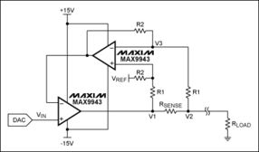
The clipper circuit is a fundamental building block in analog electronics, used to limit the amplitude of an input signal. It can be designed to clip the signal above or below a certain voltage level, effectively “cutting off” the signal beyond that point. The op amp, with its high input impedance and low output impedance, is an ideal choice for implementing a clipper circuit.
At its core, a clipper circuit using an op amp consists of an op amp, a diode, and a resistor. The diode acts as a switch, allowing the op amp to control the flow of current based on the input signal’s amplitude. The resistor sets the reference voltage, which determines the clipping level.
Types of Clipper Circuits
There are two main types of clipper circuits using op amps: positive clippers and negative clippers. The primary difference between them lies in the clipping point and the direction of the clipping action.
Positive Clipper
A positive clipper, also known as a voltage limiter, clips the input signal above a certain voltage level. When the input signal exceeds the reference voltage, the diode becomes forward-biased, and the output signal is limited to the reference voltage level. The following table illustrates the components and their functions in a positive clipper circuit:
| Component | Function |
|---|---|
| Op Amp | Amplifies the input signal and controls the diode’s biasing |
| Diode | Acts as a switch, allowing the op amp to control the flow of current |
| Resistor | Establishes the reference voltage and determines the clipping level |
Negative Clipper
A negative clipper, also known as a voltage shaver, clips the input signal below a certain voltage level. When the input signal falls below the reference voltage, the diode becomes forward-biased, and the output signal is limited to the reference voltage level. The following table illustrates the components and their functions in a negative clipper circuit:
| Component | Function |
|---|---|
| Op Amp | Amplifies the input signal and controls the diode’s biasing |
| Diode | Acts as a switch, allowing the op amp to control the flow of current |
| Resistor | Establishes the reference voltage and determines the clipping level |
Practical Applications
Clipper circuits using op amps find applications in various fields, including audio processing, signal conditioning, and communication systems. Here are some common applications:
- Audio Processing: Clipper circuits can be used to limit the amplitude of audio signals, preventing distortion and protecting speakers from damage.
- Signal Conditioning: They can be employed to remove unwanted signal components, such as noise or harmonic distortion, from a signal.
- Communication Systems: Clipper circuits can be used to limit the amplitude of transmitted signals, ensuring they remain within the specified range for proper reception.
Design Considerations
When designing a clipper circuit using an op amp, there are several factors to consider:
- Diode Selection: The choice of diode affects the clipping characteristics and the circuit’s response time.
- Op Amp Selection: The op amp should have sufficient gain and bandwidth to handle the input signal and provide the desired clipping action.
<