
Op Amp Error Amplifier: A Comprehensive Guide
Understanding the intricacies of an op amp error amplifier is crucial for anyone involved in electronic design and signal processing. This guide will delve into the details of how an op amp error amplifier functions, its applications, and the key parameters to consider when designing with this component.
What is an Op Amp Error Amplifier?

An op amp error amplifier, also known as a differential amplifier, is a type of operational amplifier circuit that compares two input voltages and amplifies the difference between them. It is widely used in various applications, including analog-to-digital converters (ADCs), digital-to-analog converters (DACs), and sensor signal conditioning.
Basic Circuit Configuration
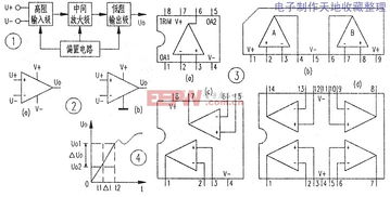
The basic configuration of an op amp error amplifier consists of two input terminals, a non-inverting input (+) and an inverting input (-), and an output terminal. The circuit typically includes a feedback resistor (Rf) and a reference voltage (Vref). The input voltages are applied to the non-inverting and inverting inputs, and the output voltage is proportional to the difference between these voltages.
| Component | Description |
|---|---|
| Op Amp | Operational amplifier with high input impedance and low output impedance |
| Input Voltage (Vin) | Input voltage applied to the non-inverting input |
| Reference Voltage (Vref) | Reference voltage applied to the inverting input |
| Feedback Resistor (Rf) | Resistor connected between the output and inverting input |
| Output Voltage (Vout) | Output voltage proportional to the difference between the input voltages |
Operation and Gain
The operation of an op amp error amplifier is based on the principle of negative feedback. When the input voltages are applied to the non-inverting and inverting inputs, the op amp tries to maintain equal voltage levels at both inputs. This results in the amplification of the difference between the input voltages, as the output voltage is proportional to the feedback resistor (Rf) and the input voltage difference.
The gain of the op amp error amplifier can be calculated using the formula:
Gain = -Rf / Rin
Where Rin is the input resistance connected to the inverting input. The negative sign indicates that the output voltage is inverted with respect to the input voltage difference.
Applications
Op amp error amplifiers find applications in various fields, including:
-
Analog-to-digital converters (ADCs): Error amplifiers are used to amplify the differential voltage output of a sensor before it is converted to a digital value.
-
Digital-to-analog converters (DACs): Error amplifiers are used to amplify the output voltage of a DAC to match the required signal level.
-
Sensor signal conditioning: Error amplifiers are used to amplify and filter the signal from a sensor, improving its accuracy and stability.
-
Signal processing: Error amplifiers are used to amplify and filter signals in various applications, such as audio and video processing.
Key Parameters to Consider
When designing with an op amp error amplifier, it is essential to consider the following key parameters:
-
Input Offset Voltage: The voltage difference between the two input terminals when no input signal is applied. A lower input offset voltage is desirable for better accuracy.
-
Input Bias Current: The current flowing into the input terminals. A lower input bias current is desirable for better accuracy and lower power consumption.
-
Open-loop Gain: The gain of the op amp when no feedback is applied. A high open-loop gain is desirable for better linearity and stability.
-
Bandwidth: The frequency range over which the op amp can amplify signals effectively. A wider bandwidth is desirable for higher-frequency applications.
In conclusion, an op amp error amplifier is a versatile