Op Amp Circuit Parts: A Comprehensive Guide
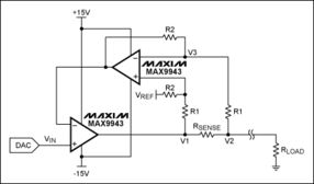
Operational amplifiers, or op-amps, are versatile electronic components widely used in various circuits. Understanding the different parts of an op-amp circuit is crucial for designing and troubleshooting electronic systems. In this article, we will delve into the various components that make up an op-amp circuit, their functions, and how they interact with each other.
1. Op-Amp IC

The heart of any op-amp circuit is the operational amplifier integrated circuit (IC). Op-amp ICs come in various configurations, such as single, dual, and quad. The most common types are the LM741, LM358, and TL081. These ICs have internal circuitry that amplifies the difference between the two input terminals, providing a high gain output.
2. Input Terminals

Op-amps have two input terminals: the inverting (-) and non-inverting (+) inputs. The inverting input is labeled with a negative sign, while the non-inverting input is labeled with a positive sign. The voltage difference between these two inputs determines the output voltage of the op-amp.
3. Output Terminal

The output terminal of an op-amp is where the amplified signal is available. It can provide both positive and negative voltages, depending on the configuration of the circuit. The output voltage is determined by the voltage difference between the input terminals and the gain of the circuit.
4. Feedback Components
Feedback components, such as resistors and capacitors, play a crucial role in shaping the behavior of an op-amp circuit. They determine the gain, bandwidth, and stability of the circuit. The feedback network can be connected in various configurations, such as voltage divider feedback, voltage follower, and inverting amplifier.
5. Power Supply
Op-amps require a power supply to operate. The power supply provides the necessary voltage and current to the op-amp IC. The power supply voltage should be higher than the maximum output voltage of the op-amp to ensure proper operation. Common power supply voltages for op-amps are +5V, +12V, and -12V.
6. Decoupling Capacitors
Decoupling capacitors are used to filter out noise and provide a stable power supply to the op-amp circuit. They are connected between the power supply and ground, close to the op-amp IC. Common values for decoupling capacitors are 0.1uF, 0.01uF, and 10uF.
7. Input Bias and Offset Current
Op-amps have input bias and offset current, which can affect the accuracy of the circuit. Input bias current is the small current that flows into the input terminals of the op-amp. Offset current is the difference between the input bias currents of the two input terminals. These currents can cause errors in the circuit, especially in low-level signal applications.
8. Input Offset Voltage
Input offset voltage is the voltage that must be applied between the input terminals to make the output voltage zero. This voltage is caused by imperfections in the op-amp’s internal circuitry. High input offset voltage can cause errors in the circuit, especially in precision applications.
9. Output Saturation
Op-amps have a maximum output voltage that they can reach. When the output voltage exceeds this limit, the op-amp is said to be in saturation. Saturation can cause distortion in the output signal and reduce the overall performance of the circuit.
10. Common Mode Rejection Ratio (CMRR)
The common mode rejection ratio (CMRR) is a measure of an op-amp’s ability to reject common-mode signals. Common-mode signals are signals that are present at both input terminals. A high CMRR ensures that the circuit is less sensitive to common-mode noise and interference.
11. Power Supply Rejection Ratio (PSRR)
The power supply rejection ratio (PSRR) is a measure of an op-amp’s ability to reject power supply noise. A high PSRR ensures that the circuit is less sensitive to fluctuations in the power supply voltage, which can cause errors in the output signal.
12. Bandwidth
The bandwidth of an op-amp is the range of frequencies over which it can amplify a signal effectively. The bandwidth is determined by the internal circuitry and the external components connected to the op-amp. A wide bandwidth is desirable for applications that require high-frequency signal
