
Understanding Op-Amp Modes: A Detailed Guide for You
Operational amplifiers, or op-amps, are versatile electronic components widely used in various applications. They are essential in signal processing, amplification, and filtering. To fully utilize an op-amp, it is crucial to understand its different modes of operation. In this article, we will delve into the various op-amp modes and their characteristics, providing you with a comprehensive guide.
What is an Op-Amp?

Before we dive into the modes of operation, let’s briefly discuss what an op-amp is. An op-amp is a high-gain, differential amplifier with two input terminals (inverting and non-inverting) and one output terminal. It is designed to amplify the difference between the two input voltages while rejecting any common-mode signals.
Op-Amp Modes of Operation
Op-amps can operate in several modes, each with its unique characteristics and applications. Let’s explore these modes in detail.
Linear Mode
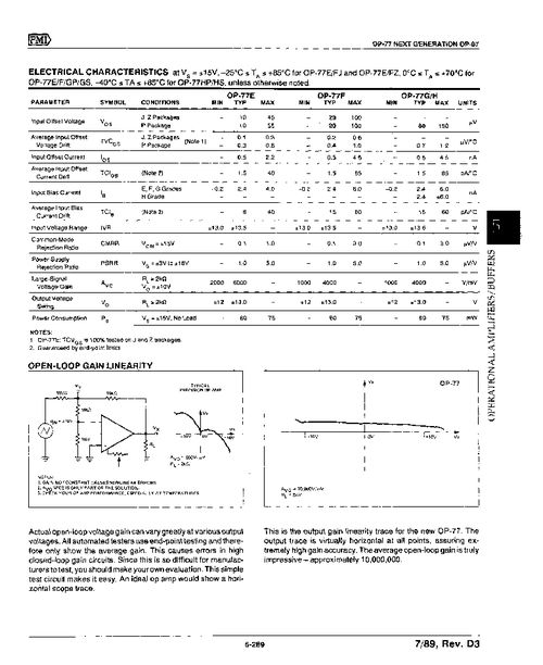
The linear mode is the most common mode of operation for op-amps. In this mode, the op-amp operates within its linear region, where the output voltage is directly proportional to the input voltage. The linear mode is characterized by the following:
| Parameter | Description |
|---|---|
| Input Offset Voltage | The voltage difference between the two input terminals when the output is at zero. |
| Input Bias Current | The current flowing into the input terminals. |
| Open-loop Gain | The gain of the op-amp when no feedback is applied. |
| Bandwidth | The frequency range over which the op-amp can amplify signals effectively. |
Non-Inverting Amplifier Mode
In the non-inverting amplifier mode, the input signal is applied to the non-inverting input terminal, and the output is taken from the output terminal. This configuration provides a voltage gain that is always positive and greater than one. The non-inverting amplifier mode is characterized by the following:
| Parameter | Description |
|---|---|
| Input Impedance | The impedance seen by the input signal. |
| Output Impedance | The impedance seen by the output signal. |
| Gain | The voltage gain of the amplifier. |
Inverting Amplifier Mode
In the inverting amplifier mode, the input signal is applied to the inverting input terminal, and the output is taken from the output terminal. This configuration provides a voltage gain that is always negative and less than one. The inverting amplifier mode is characterized by the following:
| Parameter | Description |
|---|---|
| Input Impedance | The impedance seen by the input signal. |
| Output Impedance | The impedance seen by the output signal. |
| Gain | The voltage gain of the amplifier. |
Non-Inverting Summing Amplifier Mode
In the non-inverting summing amplifier mode, multiple input signals are applied to the non-inverting input terminal, and the output is taken from the output terminal. This configuration allows the addition of multiple signals with a positive voltage gain. The non-inverting summing amplifier mode is characterized by the following:
| Parameter | Description |
|---|---|
| Input Impedance |