Pspice Op Amp: A Comprehensive Guide
When it comes to electronic design and simulation, the Pspice Op Amp is a cornerstone component. As you delve into the world of analog circuits, understanding how to use operational amplifiers (Op Amps) in Pspice becomes crucial. This guide will walk you through the intricacies of using Op Amps in Pspice, covering everything from basic configurations to advanced applications.
Understanding the Basics

Before we dive into the specifics of using Op Amps in Pspice, it’s essential to have a solid understanding of what an Op Amp is and how it functions. An operational amplifier is an electronic device that amplifies voltage signals. It has two input terminals, a non-inverting input and an inverting input, and one output terminal.
One of the key features of an Op Amp is its high input impedance and low output impedance. This means that it draws very little current from the input signal and can drive loads with high impedance. Op Amps are also characterized by their high gain, which can be adjusted by external components.
Setting Up Pspice

Before you can start using Op Amps in Pspice, you need to set up your simulation environment. Here’s a step-by-step guide to get you started:
- Open Pspice and create a new project.
- Select the appropriate library for Op Amps. The most commonly used library is the “LTspice” library, which contains a wide range of Op Amp models.
- Drag and drop an Op Amp symbol from the library onto your circuit diagram.
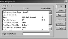
- Configure the Op Amp’s parameters, such as power supply voltage and gain, by double-clicking on the Op Amp symbol.
Basic Op Amp Configurations

There are several basic configurations for Op Amps, each with its own unique characteristics. Let’s take a look at some of the most common ones:
Inverting Amplifier
An inverting amplifier is a configuration where the input signal is applied to the inverting input terminal of the Op Amp. The output signal is the inverse of the input signal, with a gain determined by the external feedback resistor values.
| Input Signal | Output Signal |
|---|---|
| Vin | -AolVin |
Non-Inverting Amplifier
A non-inverting amplifier is a configuration where the input signal is applied to the non-inverting input terminal of the Op Amp. The output signal is the same as the input signal, with a gain determined by the external feedback resistor values.
| Input Signal | Output Signal |
|---|---|
| Vin | AolVin |
Summing Amplifier
A summing amplifier is a configuration that allows multiple input signals to be combined and amplified. The output signal is the sum of the input signals, with a gain determined by the external feedback resistor values.
| Input Signal | Output Signal |
|---|---|
| V1 | AolV1 |
| V2 | AolV2 |
| … | … |
Advanced Op Amp Applications
Op Amps can be used in a wide range of applications, from basic signal conditioning to complex control systems. Here are a few examples of advanced Op Amp applications:
Filter Design
Op Amps are commonly used in filter design, where
