Understanding Op Amp Setup: A Comprehensive Guide
Operating amplifiers, or op amps, are essential components in electronic circuits, providing a wide range of functionalities from signal amplification to filtering and oscillation. Whether you are a hobbyist or a professional engineer, understanding how to set up an op amp correctly is crucial for achieving the desired circuit performance. In this article, we will delve into the various aspects of op amp setup, covering its basics, configuration, and practical considerations.
Op Amp Basics

Before diving into the setup process, it is important to have a solid understanding of what an op amp is and how it operates. An op amp is a high-gain voltage amplifier with two input terminals: the inverting input and the non-inverting input. The output of the op amp is determined by the difference between these two input voltages, multiplied by the gain of the amplifier.
Op amps are typically represented by a symbol that consists of a triangle with two inputs and one output. The inverting input is denoted by a negative sign, while the non-inverting input is denoted by a positive sign. The output is represented by a circle with a triangle inside, indicating the amplification process.
Op Amp Configuration

There are several configurations in which an op amp can be used, each offering different functionalities. The most common configurations include the inverting amplifier, non-inverting amplifier, voltage follower, and differential amplifier. Let’s take a closer look at each of these configurations.
Inverting Amplifier
The inverting amplifier configuration is used for signal inversion and amplification. The input signal is applied to the inverting input, and the output is taken from the output terminal. The gain of the amplifier is determined by the ratio of the feedback resistor (Rf) to the input resistor (Rin). The formula for calculating the gain is: Gain = -Rf/Rin.
Non-Inverting Amplifier
The non-inverting amplifier configuration is used for signal amplification without inversion. The input signal is applied to the non-inverting input, and the output is taken from the output terminal. The gain of the amplifier is determined by the ratio of the feedback resistor (Rf) to the input resistor (Rin). The formula for calculating the gain is: Gain = 1 + Rf/Rin.
Voltage Follower
The voltage follower configuration is used to buffer a signal, maintaining the input voltage at the output. The input signal is applied to the inverting input, and the output is taken from the output terminal. The gain of the voltage follower is close to 1, with minimal signal loss.
Differential Amplifier
The differential amplifier configuration is used to amplify the difference between two input signals. The input signals are applied to the inverting and non-inverting inputs, and the output is taken from the output terminal. The gain of the differential amplifier is determined by the ratio of the feedback resistor (Rf) to the input resistor (Rin). The formula for calculating the gain is: Gain = -Rf/Rin.
Practical Considerations

When setting up an op amp, there are several practical considerations to keep in mind to ensure optimal circuit performance.
Power Supply
Op amps require a power supply to operate. The power supply voltage should be within the specified range for the particular op amp you are using. Typically, op amps operate with a dual supply, such as +5V and -5V, but some op amps can operate with a single supply voltage.
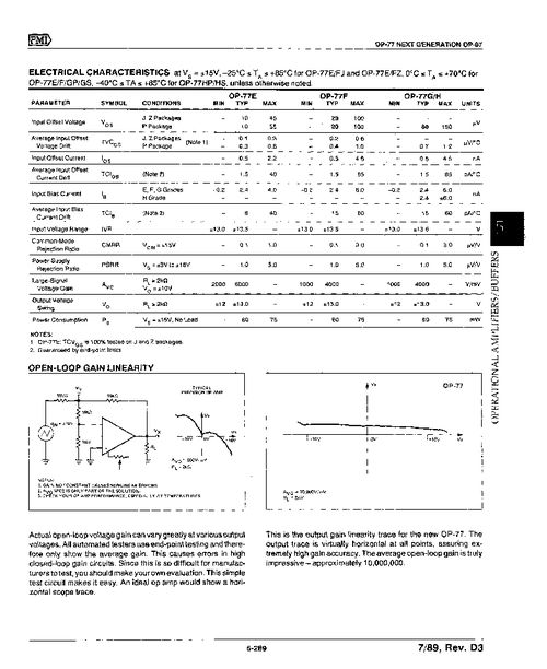
Input Offset Voltage
Op amps have an input offset voltage, which is the voltage difference between the two input terminals when the output is at zero. This offset voltage can cause errors in the circuit performance. To minimize the impact of input offset voltage, you can use an offset nulling technique, which involves adjusting the input terminals to reduce the offset voltage.
Input Bias Current
Op amps have an input bias current, which is the current flowing into the input terminals. This bias current can cause errors in the circuit performance, especially when dealing with high-impedance sources. To minimize the impact of input bias current, you can use a high-impedance input source or a buffer amplifier.
Output Current Limitation
Op amps have a maximum output current limitation, which is the maximum current that can be sourced or sunk by the output terminal. Exceeding this limitation can cause the op amp to enter saturation or damage
