
Understanding Current Sense Circuit Using Op Amp
When it comes to measuring and monitoring electrical current, a current sense circuit using an operational amplifier (op amp) is a highly effective solution. This article will delve into the intricacies of such a circuit, exploring its components, working principles, and practical applications.
Components of a Current Sense Circuit Using Op Amp

A current sense circuit using an op amp typically consists of the following components:
| Component | Description |
|---|---|
| Op Amp | The heart of the circuit, responsible for amplifying the voltage across the current sense resistor. |
| Current Sense Resistor | A resistor placed in series with the load, whose voltage drop is proportional to the current flowing through it. |
| Reference Voltage | A stable voltage source used to set the gain of the op amp and ensure accurate current measurement. |
| Feedback Resistor | Connected to the inverting input of the op amp, it determines the gain of the circuit. |
| Load | The device or circuit through which the current is being measured. |
These components work together to provide a precise and reliable measurement of the current flowing through the load.
Working Principles of a Current Sense Circuit Using Op Amp
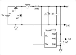
The working principle of a current sense circuit using an op amp is based on the voltage divider rule. When a current flows through the current sense resistor, a voltage drop is generated across it. This voltage drop is then amplified by the op amp, providing a proportional output voltage that represents the current flowing through the load.
Here’s a step-by-step breakdown of how the circuit operates:
- The current flows through the load and the current sense resistor in series.
- A voltage drop is generated across the current sense resistor, which is proportional to the current flowing through it.
- The voltage drop across the current sense resistor is then amplified by the op amp, using the voltage divider rule.
- The amplified voltage is then outputted by the op amp, providing a proportional representation of the current flowing through the load.
Practical Applications of Current Sense Circuits Using Op Amp
Current sense circuits using op amps find applications in various fields, including:
-
Power supplies: Monitoring and controlling the current drawn by a load in a power supply system.
-
Motor control: Measuring and regulating the current flowing through a motor to ensure optimal performance and prevent damage.
-
Battery management: Monitoring the current flowing in and out of a battery to ensure safe and efficient operation.
-
Protective circuits: Detecting excessive current and triggering a shutdown or alarm to prevent damage to the system.
Design Considerations for Current Sense Circuits Using Op Amp
When designing a current sense circuit using an op amp, several factors should be considered:
-
Accuracy: The circuit should provide a precise and accurate measurement of the current flowing through the load.
-
Bandwidth: The circuit should have a sufficient bandwidth to handle the frequency range of the current being measured.
-
Power consumption: The circuit should be designed to minimize power consumption, especially in battery-powered applications.
-
Temperature range: The circuit should be able to operate within the required temperature range.
By carefully selecting the appropriate components and designing the circuit accordingly, you can create a reliable and efficient current sense circuit using an op amp.
Conclusion
In conclusion, a current sense circuit using an op amp is a versatile and effective solution for measuring and monitoring electrical current. By understanding the components, working principles, and practical applications of such a circuit, you can design and implement a reliable current sense solution for your specific needs.