
Op 75722 Pinout Diagram: A Comprehensive Guide
When it comes to understanding the intricacies of electronic devices, the pinout diagram is a crucial tool. In this article, we delve into the details of the Op 75722 pinout diagram, providing you with a multi-dimensional introduction to this essential component.
Understanding the Op 75722

The Op 75722 is a versatile operational amplifier, widely used in various electronic circuits. It is known for its high input impedance, low output impedance, and wide bandwidth. The pinout diagram is a visual representation of the connections between the various pins of the Op 75722, making it easier to understand and use in your projects.
Pinout Diagram Overview
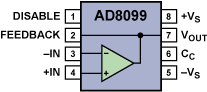
The Op 75722 pinout diagram consists of 8 pins, each serving a specific purpose. Here’s a brief overview of the pins and their functions:
| Pin Number | Function |
|---|---|
| 1 | Non-Inverting Input |
| 2 | Inverting Input |
| 3 | Output |
| 4 | Positive Supply Voltage |
| 5 | Negative Supply Voltage |
| 6 | Not Connected |
| 7 | Not Connected |
| 8 | Not Connected |
As you can see, pins 1, 2, 3, 4, and 5 are the most important ones, as they are directly involved in the amplification process. The remaining pins (6, 7, and 8) are not connected and can be left unconnected in most applications.
Connecting the Op 75722
Now that you have a basic understanding of the pinout diagram, let’s discuss how to connect the Op 75722 to your circuit. Here are the steps to follow:
- Connect the positive supply voltage (pin 4) to a suitable voltage source, such as a 9V battery or a regulated power supply.
- Connect the negative supply voltage (pin 5) to the ground of your circuit.
- Connect the non-inverting input (pin 1) to the input signal you want to amplify.
- Connect the inverting input (pin 2) to a voltage divider or a potentiometer to set the gain of the amplifier.
- Connect the output (pin 3) to the load or the next stage of your circuit.
Make sure to observe the polarity of the connections, as incorrect connections can damage the Op 75722 or your circuit.
Applications of the Op 75722
The Op 75722 is a versatile operational amplifier that can be used in various applications. Here are some common uses:
- Signal Amplification: The Op 75722 can be used to amplify low-level signals, such as those from sensors or microphones.
- Filter Design: The Op 75722 can be used to design active filters, such as low-pass, high-pass, and band-pass filters.
- Comparator: The Op 75722 can be used as a comparator to compare two voltages and provide a digital output.
- Buffer: The Op 75722 can be used as a buffer to isolate the input and output stages of a circuit.
Conclusion
The Op 75722 pinout diagram is a valuable resource for anyone working with operational amplifiers. By understanding the pinout and the various applications of the Op 75722, you can design and implement more complex electronic circuits with ease. Remember to always refer to the pinout diagram when working with the Op 75722 to ensure proper connections and optimal performance.