
Op Amp LM358 Circuit Diagram: A Comprehensive Guide
When it comes to designing circuits, the LM358 operational amplifier (op amp) is a popular choice due to its versatility and affordability. In this article, we will delve into the intricacies of the LM358 circuit diagram, exploring its various applications and configurations. Whether you are a beginner or an experienced electronics enthusiast, this guide will provide you with a comprehensive understanding of the LM358 op amp circuit diagram.
Understanding the LM358 Op Amp

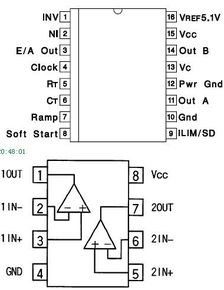
The LM358 is a dual-channel operational amplifier, meaning it contains two independent op amp circuits within a single package. Each channel operates independently, allowing for various configurations and applications. The LM358 is known for its wide input voltage range, low power consumption, and high input impedance, making it suitable for a wide range of applications, including amplification, filtering, and signal conditioning.
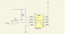
Here is a basic LM358 circuit diagram, showcasing its basic configuration:
| Component | Description |
|---|---|
| LM358 | Dual-channel operational amplifier |
| Vin+ | Positive input voltage |
| Vin- | Negative input voltage |
| Vout+ | Positive output voltage |
| Vout- | Negative output voltage |
| R1 | Input resistor |
| R2 | Feedback resistor |
As you can see, the basic LM358 circuit diagram consists of the op amp itself, along with input and feedback resistors. These components work together to amplify the input signal and provide the desired output.
Applications of the LM358 Op Amp
The LM358 op amp is widely used in various applications due to its versatility. Here are some common applications:
-
Amplification: The LM358 can be used to amplify low-level signals, such as those from sensors or microphones.
-
Filtering: The LM358 can be configured as a low-pass, high-pass, or band-pass filter, allowing for signal conditioning and noise reduction.
-
Signal Conditioning: The LM358 can be used to convert signals from one form to another, such as converting an analog signal to a digital signal or vice versa.
-
Comparator: The LM358 can be used as a comparator to compare two input voltages and provide a digital output based on the comparison result.
Configuring the LM358 Op Amp
One of the advantages of the LM358 op amp is its flexibility in configuration. Here are some common configurations:
-
Non-Inverting Amplifier: This configuration provides a gain of (1 + R2/R1), where R1 and R2 are the feedback resistors. It is commonly used for amplifying signals without phase inversion.
-
Inverting Amplifier: This configuration provides a gain of -R2/R1, where R1 and R2 are the feedback resistors. It is commonly used for phase inversion and signal inversion.
-
Non-Inverting Summing Amplifier: This configuration allows multiple input signals to be summed and amplified simultaneously.
-
Inverting Summing Amplifier: This configuration allows multiple input signals to be summed and amplified simultaneously, with phase inversion.
-
Comparator: This configuration compares two input voltages and provides a digital output based on the comparison result.
Conclusion
In conclusion, the LM358 op amp circuit diagram is a versatile and widely used component in electronics design. Its dual-channel configuration, wide input voltage range, and low power consumption make it suitable for a