Op Amp Design: A Comprehensive Guide for Aspiring Engineers
Operational amplifiers, or op amps, are fundamental components in electronic circuits. They are versatile and powerful, capable of amplifying signals, filtering noise, and performing a variety of mathematical operations. If you’re an aspiring engineer or simply curious about the intricacies of op amp design, this guide will provide you with a detailed overview of the subject.
Understanding the Basics

Before diving into the design process, it’s crucial to have a solid understanding of what an op amp is and how it functions. An op amp is an electronic device with two input terminals (inverting and non-inverting) and one output terminal. It amplifies the difference between the voltages at its input terminals, producing an output voltage that is typically much larger than the input voltage.
Op amps are often used in linear applications, such as amplifiers, filters, and oscillators. They can also be used in non-linear applications, such as comparators and voltage regulators. The key to op amp design lies in understanding its characteristics and limitations.
Characteristics of an Op Amp

Several key characteristics define an op amp’s performance and suitability for various applications. Here are some of the most important ones:
| Characteristic | Description |
|---|---|
| Open-loop gain | The gain of the op amp when no feedback is applied. This value is typically very high, often in the range of 100,000 to 1,000,000. |
| Input offset voltage | The voltage difference between the two input terminals when the output is at zero. This value is usually very small but can affect the accuracy of the circuit. |
| Input bias current | The current flowing into the input terminals of the op amp. This value is typically very low, often in the range of a few nanameters. |
| Input impedance | The resistance seen by the input terminals of the op amp. This value is typically very high, often in the range of several megohms. |
| Output impedance | The resistance seen by the output terminal of the op amp. This value is typically very low, often in the range of a few ohms. |
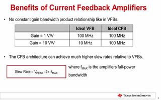
| Slew rate | The maximum rate of change of the output voltage per unit time. This value is important for applications that require fast response times. |
These characteristics can vary significantly between different op amp models, so it’s essential to choose the right one for your specific application.
Op Amp Design Process

The op amp design process involves several steps, from selecting the appropriate op amp to implementing the circuit and testing its performance. Here’s a brief overview of the process:
-
Select the appropriate op amp based on your application requirements, such as gain, bandwidth, and power supply voltage.
-
Design the circuit topology, such as an inverting amplifier, non-inverting amplifier, or filter.
-
Choose the appropriate component values for resistors, capacitors, and other components.
-
Simulate the circuit using a software tool, such as SPICE, to verify its performance.
-
Build the circuit on a breadboard or PCB and test its performance using an oscilloscope and other test equipment.
-
Tune the circuit as needed to achieve the desired performance.
Common Op Amp Topologies
There are several common op amp topologies, each with its own advantages and disadvantages. Here are some of the most popular ones:
-
Inverting Amplifier
-
Non-Inverting Amplifier
-
Summing Amplifier
-
Diff Amp
-
Filter
The inverting amplifier is the most basic op amp configuration,
